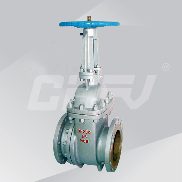
Slag gate valve
- Products
- Ball valve
- Butterfly valve
- Gate valve
- Globe Valve
- Check valve
- Anticorrosive valve
- Forged steel valve
- Regulating valve
- Hydraulic control valve
- Power station valve
- Drain valve
- Bellows valve
- Metallurgical valve
- Flame arrester and breathing valve
- Solenoid valve
- Needle valve
- Copper valve
- Ceramic valve
- Oil field valve
- Safety valve
- Actuator series

Nominal diameter: DN50 ~ 500mm
Nominal pressure: PN1.6 ~ 6.4MPa
Operating temperature: 0 ~ 100 ℃
Main material: WCB
Design and manufacture: GB12234GB2595
Flange size: GB9113JB / T79
Pressure and temperature: JB / T74GB9131
Structure length: GB / T12221
Test and Inspection: JB / T9092GB13927
PZ41H flange slag discharge valve flange bolts in
the connection, both ends of the branch pipe flange connection or butt
connection. Slag gate valve set in large diameter rolling bearings,
opening and closing easily. Slag gate valve stem by quenching and
nitriding on the surface, have good engage in corrosion, abrasion
resistance and abrasion resistance. Slag gate valve body outlet flow
channel junction type is reasonable, not slag, opening and closing
flexible, not jammed. Slag gate valve sealing material is wear-resistant
ceramic or wear-resistant alloy, abrasion resistance, durable erosion,
scratch resistance, friction, reliable sealing. Slag gate valve opening
and closing pieces of semi-sealed pair of mandatory seal, excellent
performance.
PZ41H flange drain valve products
Flange discharge valve is a common gate valve, the structural design is reasonable, easy opening and closing, and has good sealing performance and strong wear resistance, is widely used in nominal pressure PN1.6 ~ 6.4MPa, operating temperature 0 ~ 100 ℃ thermal power station water conservancy system and hydraulic system of mortar discharge system piping, to cut off or connected to the pipeline gray water mixture, slag water mixture.
PZ41H Flange Slag Gate Valve Features
1, the flange slag discharge valve flange bolts in use, both ends of the branch flange connection or butt welding connection.
2, flange drain valve set large diameter rolling bearings, opening and closing easily.
3, flange drain valve body outlet flow channel junction type is reasonable, not slag, opening and closing flexible, not stuck.
4, flange drain valve sealing material is wear-resistant ceramic or wear-resistant alloy, wear resistance, durable erosion, scratch resistance, friction, reliable sealing.
5, flange drain valve opening and closing parts with semi-seal pair of mandatory seal, excellent performance.
Flange slag valve main parts of the material description
|
Body |
WCB |
|
|
cap |
WCB |
|
|
Bracket |
WCB |
|
|
gate |
WCB + wear-resistant alloy |
WCB + ceramic |
|
Valve stem |
2Cr13 |
|
|
Seat |
WCB + wear-resistant alloy |
WCB + ceramic |
|
Seal ring |
Enhance flexible graphite |
|
|
filler |
Enhance flexible graphite |
|
|
Stem nut |
ZCuA110Fe3 |
|
Flange gate valve main shape and connection dimensions
| PN | DN | The main dimensions and connection dimensions | |||||||||
| L | D | D1 | D2 | D6 | b | f | Zd | H | D0 | ||
| 1.6MPa | 50 | 250 | 160 | 125 | 100 | - | 16 | 3 | 4-18 | 335 | 250 |
| 80 | 280 | 195 | 160 | 135 | - | 20 | 3 | 8-18 | 510 | 280 | |
| 100 | 300 | 215 | 180 | 155 | - | 20 | 3 | 8-18 | 685 | 300 | |
| 150 | 350 | 280 | 240 | 210 | - | 24 | 3 | 8-23 | 790 | 300 | |
| 200 | 400 | 335 | 295 | 265 | - | 26 | 3 | 12-23 | 885 | 350 | |
| 250 | 450 | 405 | 355 | 320 | - | 30 | 3 | 12-25 | 1015 | 400 | |
| 300 | 500 | 460 | 410 | 375 | - | 30 | 3 | 12-25 | 1190 | 450 | |
| 350 | 550 | 520 | 470 | 435 | - | 34 | 4 | 16-25 | 1350 | 500 | |
| 400 | 600 | 580 | 525 | 485 | - | 36 | 4 | 16-25 | 1460 | 500 | |
| 450 | 650 | 640 | 585 | 545 | - | 40 | 4 | 20-30 | 1620 | 550 | |
| 500 | 700 | 705 | 650 | 608 | - | 44 | 4 | 20-34 | 1800 | 550 | |
| 2.5MPa | 50 | 250 | 160 | 125 | 100 | - | 20 | 3 | 4-18 | 335 | 250 |
| 80 | 280 | 195 | 160 | 135 | - | 22 | 3 | 8-18 | 510 | 280 | |
| 100 | 300 | 230 | 190 | 160 | - | 24 | 3 | 8-23 | 685 | 300 | |
| 150 | 350 | 300 | 250 | 218 | - | 30 | 3 | 8-25 | 790 | 300 | |
| 200 | 400 | 360 | 310 | 278 | - | 34 | 3 | 12-25 | 885 | 350 | |
| 250 | 450 | 425 | 370 | 332 | - | 36 | 3 | 12-30 | 1015 | 400 | |
| 300 | 500 | 485 | 430 | 390 | - | 40 | 4 | 16-30 | 1190 | 450 | |
| 350 | 550 | 550 | 490 | 448 | - | 44 | 4 | 16-34 | 1350 | 500 | |
| 400 | 600 | 610 | 550 | 505 | - | 48 | 4 | 16-34 | 1460 | 500 | |
| 450 | 650 | 660 | 600 | 555 | - | 50 | 4 | 20-34 | 1620 | 550 | |
| 500 | 700 | 730 | 660 | 610 | - | 52 | 4 | 20-41 | 1800 | 550 | |
| 4.0MPa | 50 | 250 | 160 | 125 | 100 | 88 | 20 | 3 | 4-18 | 340 | 250 |
| 80 | 310 | 195 | 160 | 135 | 121 | 22 | 3 | 8-18 | 508 | 300 | |
| 100 | 350 | 230 | 190 | 160 | 150 | 24 | 3 | 8-23 | 680 | 300 | |
| 150 | 450 | 300 | 250 | 218 | 204 | 30 | 3 | 8-25 | 800 | 400 | |
| 200 | 550 | 375 | 320 | 282 | 260 | 38 | 3 | 12-30 | 875 | 500 | |
| 250 | 650 | 445 | 385 | 345 | 313 | 42 | 3 | 12-34 | 1010 | 500 | |
| 300 | 750 | 510 | 450 | 408 | 364 | 46 | 4 | 16-34 | 1180 | 550 | |
| 350 | 850 | 570 | 510 | 465 | 422 | 52 | 4 | 16-34 | 1145 | 600 | |
| 400 | 950 | 655 | 585 | 535 | 474 | 58 | 4 | 16-41 | 1280 | 600 | |
| 450 | 1050 | 680 | 610 | 560 | 524 | 60 | 4 | 20-41 | 1415 | 700 | |
| 500 | 1150 | 755 | 670 | 612 | 576 | 62 | 4 | 20-48 | 1560 | 750 | |
| 6.4MPa | 50 | 250 | 175 | 135 | 105 | - | 26 | 3 | 4-23 | 340 | 250 |
| 80 | 310 | 210 | 170 | 140 | - | 30 | 3 | 8-23 | 508 | 300 | |
| 100 | 350 | 250 | 200 | 168 | - | 32 | 3 | 8-25 | 680 | 300 | |
| 150 | 450 | 340 | 280 | 240 | - | 38 | 3 | 8-34 | 800 | 400 | |
| 200 | 550 | 405 | 345 | 300 | - | 44 | 3 | 12-34 | 875 | 500 | |
| 250 | 650 | 470 | 400 | 352 | - | 48 | 3 | 12-41 | 1010 | 500 | |
| 300 | 750 | 530 | 460 | 415 | - | 54 | 4 | 16-41 | 1180 | 550 | |
| 350 | 850 | 595 | 525 | 475 | - | 60 | 4 | 16-41 | 1145 | 600 | |
| 400 | 950 | 670 | 585 | 525 | - | 66 | 4 | 16-48 | 1280 | 600 | |
| 450 | 1050 | 715 | 630 | 570 | - | 70 | 4 | 20-48 | 1415 | 700 | |
| 500 | 1150 | 800 | 705 | 610 | - | 76 | 4 | 20-54 | 1560 | 750 | |


