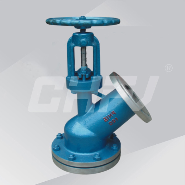
Upper and lower display discharge valve
- Products
- Ball valve
- Butterfly valve
- Gate valve
- Globe Valve
- Check valve
- Anticorrosive valve
- Forged steel valve
- Regulating valve
- Hydraulic control valve
- Power station valve
- Drain valve
- Bellows valve
- Metallurgical valve
- Flame arrester and breathing valve
- Solenoid valve
- Needle valve
- Copper valve
- Ceramic valve
- Oil field valve
- Safety valve
- Actuator series

Nominal diameter: DN50 ~ 150mm
Nominal pressure: PN1.0 ~ 6.4MPa
Suitable temperature: -29 ~ 650 ℃
Main material: WCB, ZG1Cr18Ni9Ti, ZG1Cr18Ni12Mo2Ti, CF8, CF8M, CF3, CF3M
Design and manufacture: GB12234-89
Structure length: GB12221-89
Flange size: JB / T79-94
Inspection and test: GB13927
Manual discharge valve performance and purpose
The
valve is easy to operate, open the freedom, flexible and reliable
movement; valve assembly and maintenance simple, reasonable sealing
structure, sealing ring replacement convenient and practical.
Manual discharge valve structure and principle:
The
valve is mainly composed of 1. Valve body, 2. Valve flap, 3. Seal, 4.
Stem, 5. Bracket, 6. Valve gland, 7. Hand wheel, 8. Law Blue, 9. Nut,
10. Set screws and other components, handwheel clockwise, the valve
closed, the stem moves upward, the valve is on the exhibition, the
handwheel clockwise, the valve closed, the valve stem down, the valve
For the exhibition valve
Manual discharge valve main parts material
| Part Name | ZG1Cr18Ni9Ti series | ZG00Cr18Ni10 series | ZG1Cr18Ni12MO 2 Ti series | ZG00Cr17Ni14MO 2 series | WCB series |
| Body / bonnet | ZG1Cr18Ni9Ti | ZG00Cr18Ni10 | ZG1Cr18Ni12MO 2 Ti | ZG00Cr17Ni14MO 2 | WCB |
| Valve stem | ZG1Cr18Ni9Ti | ZG00Cr18Ni10 | ZG1Cr18Ni12MO 2 Ti | ZG00Cr17Ni14MO 2 | WCB |
| Disc | ZG1Cr18Ni9Ti | ZG00Cr18Ni10 | ZG1Cr18Ni12MO 2 Ti | ZG00Cr17Ni14MO 2 | WCB |
| Gasket | 304 + PTFE | 304L + PTFE | 316 + PTFE | 316L + PTFE | Graphite +304 |
| Stud | 1Cr17Ni2 | 1Cr17Ni2 | 1Cr17Ni2 | 1Cr17Ni2 | 35CrMoA |
| Nut | 1Cr18Ni9Ti | 1Cr18Ni9Ti | 1Cr18Ni9Ti | 1Cr18Ni9Ti | 45 |
Upper discharge valve connection size
| DN | On the flange | On the flange | Under the flange | Sealing seat | ||
| D1 | D2 | D3 | D4 | D5 | D6 | |
| 25 | 115 | 80 | 115 | 85 | - | - |
| 32 | 135 | 100 | 135 | 100 | - | - |
| 40 | 145 | 110 | 145 | 110 | 80 | 60 |
| 50 | 165 | 125 | 160 | 125 | 85 | 70 |
| 65 | 180 | 145 | 180 | 145 | 130 | 85 |
| 80 | 195 | 160 | 195 | 160 | 135 | 95 |
| 100 | 215 | 180 | 215 | 180 | 160 | 130 |
| 125 | 245 | 210 | 245 | 210 | 160 | 140 |
| 150 | 280 | 240 | 280 | 240 | 185 | 165 |
| 200 | 335 | 295 | 335 | 295 | / | / |
Unfolded discharge valve connection size
| DN | On the flange | On the flange | Under the flange | Sealing seat | ||
| D1 | D2 | D3 | D4 | D5 | D6 | |
| 25 | 115 | 85 | 135 | 100 | 70 | 40 |
| 32 | 135 | 100 | 145 | 110 | 75 | 55 |
| 40 | 145 | 110 | 160 | 125 | 100 | 65 |
| 50 | 165 | 125 | 180 | 145 | 85 | 70 |
| 65 | 180 | 145 | 195 | 160 | 135 | 90 |
| 80 | 195 | 160 | 215 | 180 | 155 | 130 |
| 100 | 215 | 180 | 245 | 210 | 195 | 135 |
| 125 | 245 | 210 | 280 | 245 | 180 | 145 |
| 150 | 280 | 240 | 335 | 295 | 210 | 185 |
| 200 | 335 | 295 | 405 | 355 | / | / |


